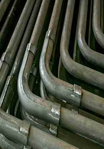
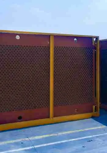
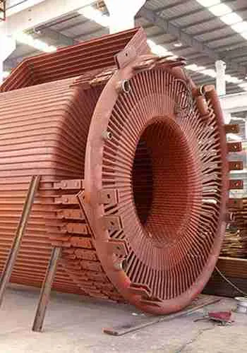
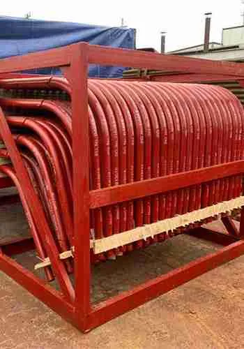
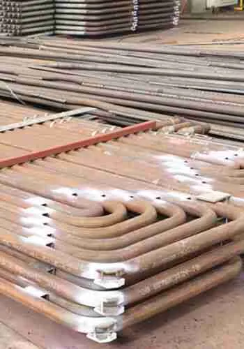
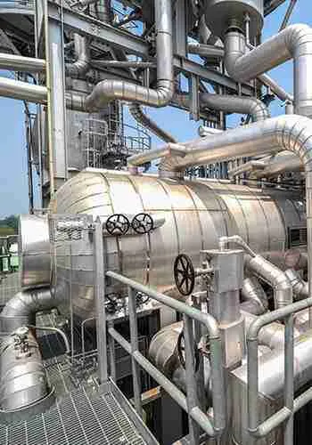
As an essential unit equipment in industrial production processes, boiler heat exchangers are widely applied in engineering fields such as oil, pharmaceutical, and refrigeration. In this issue, we will explore the structure and performance characteristics of heat exchangers.
I. Classification of Boiler Heat Exchangers
1. Classification by Application
(1) Heater: Used to heat fluids to a required temperature without phase change occurring in the heated fluid.
(2) Preheater: Used to preheat fluids to improve the overall efficiency of a process unit.
(3) Superheater: Used to heat saturated steam to achieve a superheated state.
(4) Evaporator: Used to heat liquids, causing them to vaporize.
(5) Reboiler: A specialized equipment for distillation processes, used to heat condensed liquid for revaporization.
(6) Cooler: Used to cool fluids to a required temperature.
(7) Condenser: Used to condense saturated steam, releasing latent heat for liquefaction.
2. Classification by Heat Transfer Surface Shape and Structure
(1) Tubular Heat Exchangers: Transfer heat through tube walls. Subtypes include:
- Shell-and-Tube Heat Exchangers
- Double-Pipe Heat Exchangers
- Coiled Tube Heat Exchangers
- Finned Tube Heat Exchangers
Tubular heat exchangers are the most widely used.
(2) Plate Heat Exchangers: Transfer heat through plate surfaces. Subtypes include:
- Flat Plate Heat Exchangers
- Spiral Plate Heat Exchangers
- Plate-Fin Heat Exchangers
- Heat Plate Exchangers
(3) Special Type Heat Exchangers: Designed with unique structures for specific process requirements, e.g.:
- Rotary Heat Exchangers
- Heat Pipe Heat Exchangers
3. Classification by Construction Material
(1) Metallic Material Heat Exchangers: Constructed from metals including:
- Carbon Steel
- Alloy Steel
- Copper and Copper Alloys
- Aluminum and Aluminum Alloys
- Titanium and Titanium Alloys
High thermal conductivity ensures superior heat transfer efficiency. Predominantly used in industry.
(2) Non-Metallic Material Heat Exchangers: Constructed from non-metallic materials including:
- Graphite
- Glass
- Plastics
- Ceramic
Primarily used for corrosive media. Lower thermal conductivity results in reduced heat transfer efficiency.
II. Structure and Performance Characteristics of Tubular Heat Exchangers
1. Shell-and-Tube Heat Exchangers
Shell-and-tube heat exchangers, also known as tubular heat exchangers, are a versatile and standardized type of heat exchange equipment. They offer advantages such as simple structure, robust durability, low cost, wide material compatibility, easy cleaning, and strong adaptability. They are the most widely used and dominant type in heat exchange applications. Shell-and-tube heat exchangers are classified into the following types based on structural features.
(1) Fixed Tube Sheet Heat Exchanger
Composed of a shell, tube bundle, headers, tube sheets, baffles, and nozzles. Its structural feature is that two tube sheets are welded to either end of the shell, and the tube bundle is fixed at both ends to these tube sheets. The exchanger is divided into two parts: the channel inside the tubes and its connected ends form the tube side, while the channel outside the tubes and its connections form the shell side. Cold and hot fluids flow continuously through the tube side and shell side, respectively. The fluid in the tube side is the tube-side fluid, and the fluid in the shell side is the shell-side fluid.
If the tube-side fluid passes through the tube side once, it is called a single tube pass. When a large heat transfer area requires many tubes, the tube bundle is often divided into multiple groups to increase fluid velocity. Fluid passing through the tubes multiple times sequentially is called a multi-tube pass. Tube passes can be 2, 4, 6, or 8. While more passes increase tube-side velocity and convective heat transfer coefficient, they also raise flow resistance. Thus, the number of tube passes should not be excessive; 2-pass configurations are most common.
If the shell-side fluid passes through the shell side once, it is a single shell pass. To increase shell-side velocity, longitudinal baffles parallel to the tube bundle axis can divide the shell side into multiple passes. The number of shell passes equals the number of times the shell-side fluid travels back and forth along the shell axis.
Multi-pass designs increase shell-side velocity, extend flow paths, and enhance turbulence, improving heat transfer. However, multi-shell passes increase flow resistance and complicate manufacturing/installation, making them less common. Instead, baffles are typically used to improve shell-side heat transfer by enhancing turbulence.
Advantages: Simple and compact structure. Maximum tube count and minimal bypass for a given shell diameter. Individual tubes can be replaced, and tube-side cleaning is easy.
Disadvantages: Mechanical cleaning of the shell side is impossible. Significant temperature differences (>50°C) between tubes and shell cause thermal stress, requiring an expansion joint on the shell, which limits shell-side pressure.
Applications: Suitable for clean, non-fouling shell-side fluids, moderate temperature differences, or large temperature differences with low shell-side pressure.
(2) Floating Head Heat Exchanger
Its structural feature is that one tube sheet is not fixed to the shell, allowing axial free expansion (called the floating head).
Advantages: No thermal stress between tubes and shell during expansion. The tube bundle can be removed for easy cleaning of both tube and shell sides.
Disadvantages: Complex structure, high material consumption, and cost. Leakage may occur if the seal between the floating head cover and floating tube sheet fails, mixing the two fluids.
Applications: Suitable for large tube-shell temperature differences or fouling-prone shell-side fluids.
(3) U-Tube Heat Exchanger
Features a single tube sheet with U-shaped tubes fixed at both ends to this sheet. The tube bundle expands freely, eliminating thermal stress during differential expansion.
Advantages: Simple structure, single tube sheet, fewer sealing surfaces, reliable operation, low cost. Tube bundle can be removed for easy shell-side cleaning.
Disadvantages: Difficult tube-side cleaning. Low tube sheet utilization due to tube bending radius. Large inner tube pitch causes shell-side bypass. Damaged inner tubes cannot be replaced, increasing scrap rates.
Applications: Suitable for large tube-shell temperature differences, fouling-prone shell-side fluids, and clean, non-fouling tube-side fluids under high temperature/pressure/corrosion. High-pressure/corrosive fluids typically flow through tubes to minimize high-pressure volume and sealing complexity.
(4) Stuffing Box Heat Exchanger
Features one tube sheet fixed to the shell and the other sealed by a stuffing box. The tube bundle expands freely without thermal stress.
Advantages: Simpler than floating head type, easier manufacturing, lower material consumption/cost. Tube bundle removable for cleaning both sides. Easy maintenance.
Disadvantages: Stuffing box pressure rating limited (<4.0 MPa). Shell-side fluid may leak externally, making it unsuitable for flammable, toxic, or expensive media.
Applications: Suitable for large tube-shell temperature differences or fouling-prone media requiring frequent cleaning at low pressure.
(5) Kettle Type Heat Exchanger
Features an evaporation space in the upper shell, doubling as a steam chamber. Tube bundles can be fixed tube sheet, floating head, or U-tube type.
Advantages: Easy cleaning/maintenance. Handles dirty or fouling media. Withstands high temperature/pressure.
Applications: Liquid-vapor heat exchange. Can serve as a simple waste heat boiler.
Beyond these five types, shell-and-tube heat exchangers also include insert tube heat exchangers and sliding tube sheet heat exchangers.
2.Coiled Tube Heat Exchangers
Coiled tube heat exchangers are the simplest in structure and most convenient to operate among tubular heat exchangers. Typically classified by heat transfer method into immersed type and spray type coiled tube heat exchangers.
(1) Immersed Coiled Tube Heat Exchanger
This exchanger is usually formed by bending metal tubes into container-adapted shapes immersed in the vessel’s liquid. Heat exchange occurs between fluids inside and outside the tubes. Common coiled tube configurations include spiral, serpentine, and helical arrangements.
Advantages: Simple structure, low cost, easy corrosion protection, and high-pressure resistance. Disadvantages: Due to the container volume being significantly larger than the tube volume, the heat transfer film coefficient of the shell-side fluid is low, often requiring agitators to improve heat transfer efficiency.
(2) Spray Type Coiled Tube Heat Exchanger
Primarily used for cooling hot fluids inside tubes. Coils are fixed vertically on a support frame. Hot fluid enters through bottom tubes and exits from top tubes. Cooling water is uniformly sprayed onto upper coils via overhead distributors, flows down external surfaces, cascades onto lower coils, and collects in a bottom pan. Installed outdoors where water evaporation enhances cooling.
Compared to immersed type, spray type offers easier maintenance/cleaning and better heat transfer. Disadvantages: Large footprint, high water consumption, and uneven spray distribution. Widely used in refrigeration units and small cooling systems due to simplicity and operational convenience.
3.Double-Pipe Heat Exchangers
Double-pipe heat exchangers consist of two concentric straight pipes of different diameters. The inner pipes are connected sequentially by U-bends, while outer pipes are interconnected (structure shown in Fig. 4-43). Each concentric segment is called a “pass,” with pass count adjustable per heat transfer requirements. One fluid flows through the inner pipe, the other through the annular space, with the inner pipe wall serving as the heat transfer surface.
Advantages: Simple structure; high-pressure capability; scalable heat transfer area; adjustable pipe diameters to increase fluid velocity; counter-current flow enhances heat transfer. Disadvantages: High metal consumption per unit heat transfer area; numerous pipe joints complicate maintenance and cleaning. Suitable for high-temperature, high-pressure, and low-flow fluid heat exchange.
4.Finned Tube Heat Exchangers
Finned tube heat exchangers (or tube-fin heat exchangers) feature externally or internally attached fins on tubes. Common fins include longitudinal and transverse types, with several industrial variants below.
Fins must bond tightly to tubes; otherwise, significant contact thermal resistance compromises heat transfer. Connection methods: heat shrinking, embedding, tension winding, and welding. Finned tubes may also be manufactured via integral rolling, casting, or machining.
Chemical processes often involve gas heating/cooling. Gases exhibit low convective heat transfer coefficients. When exchanging heat with condensing steam or cooling water, gas-side resistance dominates. Enhancement requires:
① Increasing gas-side convective area via fins
② Enhancing gas turbulence to reduce thermal resistance
This improves gas-side heat transfer coefficients.
Fin installation increases cost, but finned tube exchangers are economically viable when fluid convective coefficients exceed a 3:1 ratio. Widely used as air coolers, they replace water cooling—enabling use in arid regions and offering economic benefits even where water is abundant.
III. Structure and Performance Characteristics of Plate Heat Exchangers
1.Flat Plate Heat Exchanger
Flat plate heat exchangers (abbreviated as plate heat exchangers) consist of parallel thin metal plates clamped in a frame. Gaskets between adjacent plates form sealed fluid channels, with channel dimensions adjustable via gasket thickness. Each plate has four corner holes: two connected to the flow path and two isolated. Hole positions alternate between plates, creating separate channels for cold/hot fluids which flow alternately on either side of plates for heat transfer.
Plates are the core components. To ensure uniform flow, increase surface area, and enhance turbulence, plates are pressed with corrugated patterns (e.g., horizontal, herringbone, or arc-shaped).
Advantages: Compact structure with high surface area-to-volume ratio; flexible assembly for adjusting plates; corrugations boost turbulence and heat transfer efficiency; easy disassembly for maintenance/cleaning.
Disadvantages: Limited capacity; operating pressure/temperature constrained by gasket materials (typically ≤2.5 MPa, -35°C~200°C).
Applications: Frequent-cleaning scenarios with space constraints.
2.Spiral Plate Heat Exchanger
Formed by coiling two parallel metal plates spaced apart into concentric spiral channels. Spacer studs maintain channel clearance, and covers are welded to both sides. Fluids flow through separate channels, exchanging heat via the plates.
Classified by flow pattern:
(1) Type I: Both spiral channels fully welded. Fluids flow counter-currently (cold: periphery→center; hot: center→periphery). Mainly for liquid-liquid heat transfer.
(2) Type II: One spiral channel welded, the other open. One fluid flows spirally, the other axially. Suitable for large flow differentials (e.g., condensers, gas coolers).
(3) Type III: One fluid flows spirally, the other axially-spirally. Designed for vapor condensation.
(4) Type G (Tower-mounted): Vertically installed atop towers. Vapor enters bottom, rises through central pipe, reverses at top, and condenses axially downward through spiral channels.
Advantages: Turbulence achieved at low Reynolds numbers; high allowable velocity → high heat transfer coefficients; anti-fouling due to centrifugal force; long flow paths enable small-temperature-difference operation; compact (3× surface area/volume vs. shell-and-tube).
Disadvantages: Limited operating conditions (≤2 MPa, ≤400°C); difficult repair if leaked.
3.Heat Plate Heat Exchanger
A novel high-efficiency plate exchanger with “heat plates” as basic units. Formed by spot-/roll-welding multiple metal layers into patterned flow channels under equal flow resistance principle. Sealed edges and gas-pressurized interlayers optimize flow. Plate thickness/layers vary (e.g., unequal-thickness bilayer, equal-thickness quadruple-layer) for customizable surfaces.
Advantages: Optimal flow state → low resistance & high efficiency; customizable shapes/materials.
Applications: Heating, insulation, drying, condensation. Broad prospects as an emerging technology.
IV. Structure and Performance Characteristics of Heat Pipe Heat Exchangers
Heat pipe heat exchangers, with heat pipes as heat transfer units, are novel high-efficiency devices comprising a shell, heat pipes, and baffles. The heat pipe—a high-thermal-conductivity element—is a vacuum container consisting of a casing, wick structure, and working fluid. After evacuating and filling with working fluid, sealing forms a heat pipe. When heated at one end, the fluid absorbs heat and vaporizes. Vapor carrying latent heat rapidly transfers to the opposite end under pressure difference, releases latent heat to condense, and condensate returns to restart the cycle.
Heat pipes are classified by condensate return mechanism:
Wick heat pipes: Condensate returns via capillary action (operates in zero gravity).
Gravity heat pipes: Condensate returns by gravity (unidirectional; typically vertical).
Centrifugal heat pipes: Condensate returns via centrifugal force (for rotating parts).
Heat pipes are classified by operating temperature:
Cryogenic (<200K): Nitrogen, hydrogen, neon, oxygen, methane, ethane.
Low-temperature (200–550K): Freon, ammonia, acetone, ethanol, water.
Medium-temperature (550–750K): Dowtherm A, mercury, cesium, water, potassium-sodium mixtures.
High-temperature (>750K): Potassium, sodium, lithium, silver.
Heat transfer characteristics: Heat transmission occurs through boiling vaporization, vapor flow, and vapor condensation. Boiling/condensation exhibit high convective heat transfer coefficients with minimal vapor flow resistance, enabling large heat flux at small temperature differences. Thus, ideal for small-ΔT applications and high isothermal requirements.
Advantages: Simple structure, long lifespan, high reliability, broad applicability (gas-gas, gas-liquid, liquid-liquid heat exchange).