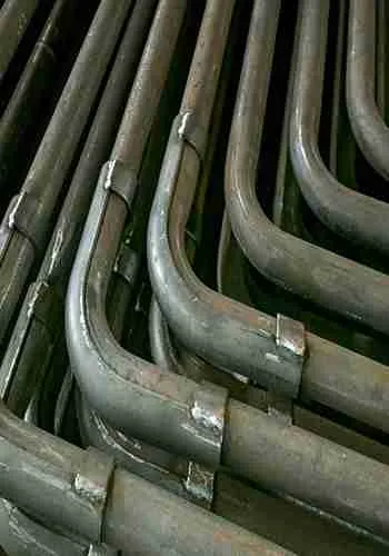
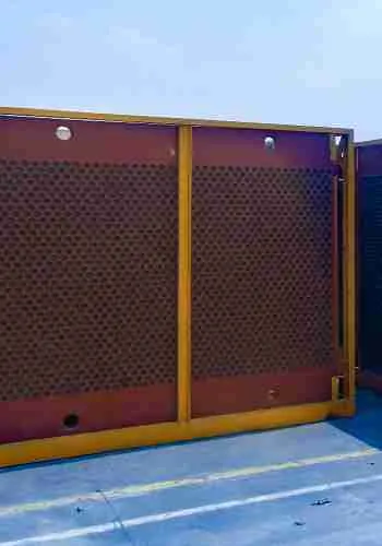
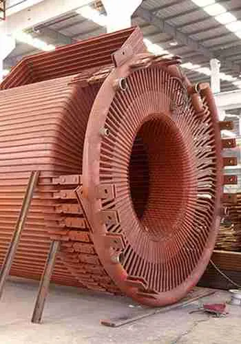
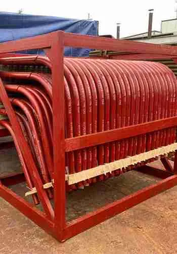
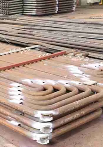
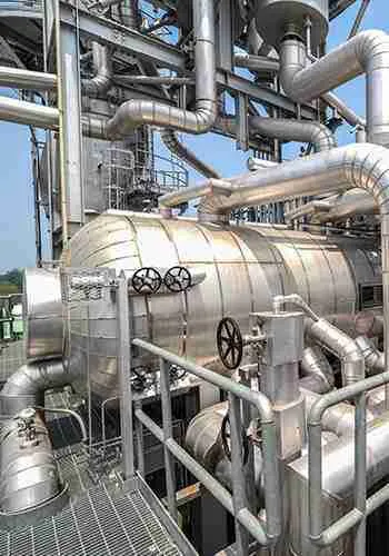
Pin-studded tubes are critical heating surface components in circulating fluidized bed (CFB) boilers, heat recovery steam generators (HRSGs), and selective catalytic reduction (SCR) denitrification systems. Pins welded onto the tube wall anchor refractory castables, providing erosion resistance, thermal insulation, and structural protection for the tubing. Manufacturing precision, stud-weld strength, and dimensional stability directly determine boiler operational safety, refractory service life, and heat transfer efficiency. To standardize production, eliminate defects (such as stud detachment, cold welds, thermal distortion, and stud misalignment), and establish a benchmark for mass production, quality acceptance, and process optimization, this scheme outlines the core manufacturing steps and quality control protocol based on boiler industry standards and field experience.
I. Core Manufacturing Process Guidelines for Boiler Pin-Studded Tubes
The production of pin-studded tubes involves seven core stages: base tube pretreatment, stud selection and cutting, fixture setup and positioning, automatic stud welding, post-weld alignment, non-destructive testing (NDT), and surface preservation. Strict process control at each stage is essential to ensure product quality.
1. Base Tube Pretreatment
Base tubes serve as the structural substrate and are typically made of boiler-grade heat-resistant steels such as 20G, 15CrMoG, or 12Cr1MoVG. Pretreatment ensures the removal of surface impurities and oxide scale to facilitate full fusion during welding.
Material Inspection: Verify material test certificates (MTCs) and dimensional specs upon receipt. Inspect tubes to ensure they are free of cracks, dents, laps, or excessive corrosion. Non-compliant tubes must be rejected.
Surface Cleaning: Mechanically grind the welding zones to remove rust, oil, mill scale, and paint. Clean a margin of at least 20 mm around each weld point until a uniform metallic sheen is achieved.
Straightening: Straighten bent or deformed tubes using dedicated equipment. Maintain a straightness tolerance of $\le 1.5\text{ mm/m}$ and a overall twist tolerance of $\le 2.0\text{ mm}$ per full tube length to prevent stud alignment offset and uneven stress distribution during welding.
Storage and Staging: Store pretreated tubes in a clean, dust-free environment. Perform stud welding within 24 hours of pretreatment to prevent re-oxidation.
2. Stud Selection and Cutting
Stud material, geometry, and dimensional accuracy determine anchor strength within the castable lining and performance at elevated temperatures.
Material Selection: Use carbon steel studs (Q235B or 20#) for low-to-medium temperature applications. Use heat-resistant stainless steel studs (304 or 310S) for high-temperature, high-erosion environments such as CFB boilers to prevent high-temperature oxidation and premature fracture.
Precision Cutting: Cut studs using dedicated CNC cutting machinery. Manual oxy-fuel cutting is prohibited to ensure flat, burr-free end faces and avoid fusion defects or slag inclusion.
Dimensional Tolerances: For standard studs (φ8mm to φ16mm in diameter), control length tolerance within ±0.5mm and end-face squareness within 0.3°. Conduct first-article inspection (FAI) before mass cutting.
Sorting and Cleaning: Inspect and discard bent, deformed, or defective studs. Clean oil and oxide scale from stud surfaces to ensure a clean contact area.
3. Fixture Setup and Positioning
Uniform stud pitch and precise location ensure balanced load distribution and uniform castable adherence.
Fixture Calibration: Calibrate the automated welding rig before production. Set lateral and longitudinal positioning scales and secure clamping mechanisms to prevent tube movement or vibration during welding.
Layout Tolerances: Maintain transverse pitch, longitudinal pitch, and edge margin tolerances within ±1.0mm. Ensure uniform alignment without offset or density variations.
Curved and Bent Tubes: Use segmented positioning fixtures for bends or custom configurations. Adjust fixture angle to follow the tube radius, ensuring studs remain perpendicular and properly seated on the tube surface.
First-Article Inspection (FAI): Perform trial welds after fixture setup to verify layout accuracy and weld positioning. Lock processing parameters prior to mass production.
4. Automatic Stud Welding
Automated Drawn Arc Stud Welding / Resistance Stud Welding is required to achieve high consistency and bond strength.
Parameter Settings: Select welding current, dwell time, and plunge pressure based on tube and stud metallurgy:
Carbon Steel Studs on 20G Tubes: Current 800-1200 A, Dwell Time 0.3-0.5s, Plunge Pressure 0.25-0.35 MPa.
Stainless Steel Studs on Alloy Steel Tubes: Current 1100-1500 A, Dwell Time 0.4-0.6 s.
Process Execution: The system automatically executes arc ignition, pool formation, and forging (plunge). Avoid manual interference during execution. Inspect stud form after completing each tube to prevent incomplete fusion, cold welds, burn-through, or deformation.
Heat Input Control: Manage interpass temperatures to avoid localized annealing, wall thinning, undercut, or base metal degradation.
5. Post-Weld Realignment and Formatting
Welding heat input can induce minor tube distortion and stud angular deviation.
Stud Realignment: Adjust tilted or misaligned studs using dedicated alignment tools. Ensure perpendicularity to the tube wall within an angular error of ≤1.0°.
Tube Straightening: Perform secondary straightening on tubes with thermal distortion to meet final installation tolerances.
Handling Precautions: Heavy impacts or hammering are prohibited during realignment to prevent micro-cracking at the stud root or joint loosening.
6. Post-Processing and Surface Protection
Cleaning: Remove weld spatter, flash, and burrs. Grind weld joints smooth to eliminate stress risers and prevent refractory wear.
Preservation: Apply anti-corrosion primer to carbon steel assemblies. Protect stainless steel assemblies with dust covers.
Storage: Store finished tubes off the ground on timber dunnage in a dry, ventilated indoor facility to prevent moisture buildup and rust formation.
Traceability Tagging: Tag all finished products with specification, material grade, heat number, production batch, and inspection stamp.
II. Welding Quality Control Scheme
Welding defects are the primary cause of field failures in pin-studded tubes. This quality assurance framework spans pre-weld setup, in-process monitoring, and post-weld inspection to address risks such as cold welding, stud detachment, lack of fusion, cracking, undercut, and excessive spatter.
1. Pre-Weld Quality Control
Personnel Qualification: Operators must hold valid certifications in automated stud welding and pass a pre-production practical test.
Equipment Verification: Inspect current output, dwell timing, pneumatic/hydraulic plunge systems, and clamp alignment daily prior to production. Replace worn components immediately.
Material Verification: Confirm tube and stud material heat numbers against design drawings. Verify surface cleanliness of all contact areas.
Process Briefing: Issue approved Weld Procedure Specifications (WPS) tailored to specific material combinations. Unapproved parameter modifications are prohibited.
2. In-Process Quality Monitoring
Parameter Monitoring: Continuously monitor arc current, dwell time, and plunge force. Pause production immediately if parameter drift occurs. Log parameters hourly.
Visual Line Inspection: Inspect finished tubes for missed welds, cold welds, stud tilt, excessive spatter, and tube wall undercut.
Thermal Stress Control: Pace welding sequences to prevent excessive heat buildup, severe residual stress, and thermal distortion.
Sampling Protocol: Randomly sample 3 out of every 50 completed tubes for immediate visual and preliminary mechanical checks.
3. Post-Weld Inspection and Testing Standards
Quality acceptance requires a four-tier inspection procedure:
A.Visual Inspection (100%): Weld collars must be full and uniform (360° flash fillet) without porosity, slag inclusions, cracks, or lack of fusion. Tube walls must be free of undercut, burn-through, or gouges.
B.Dimensional Verification: Check stud pitch, edge distance, verticality, and overall tube straightness against engineering drawings.
C.Mechanical Testing:
a)Hammer Test: Perform a bend/hammer test on selected sample studs (bend 15°-30°. The weld joint must show no signs of cracking or detachment.
b)Tensile Testing: Batch samples must meet specified tensile strength limits (Carbon Steel ≥300MPa; Stainless Steel ≥450MPa).
D.Non-Destructive Testing (NDT): For high-pressure/high-temperature boiler tubes, perform Liquid Penetrant Testing (PT) on stud root zones to detect subsurface micro-cracks or lack of sidewall fusion. Maintain inspection records for full traceability.
4. Defect Rectification and Prevention Guidelines
Defect Type Root Cause Preventive Measure Rectification Procedure
Cold Weld / Stud Detachment Insufficient current, dirty contact surface, low plunge force. Thoroughly clean joint surfaces; optimize heat input parameters; increase plunge pressure. Grind off defective stud, clean base metal, re-weld, and re-inspect.
Stud Root Cracking High heat input, excessive restraint stress, base/stud material mismatch. Control interpass temperature and welding pace; strictly match filler/stud metallurgy. Scrap tube section. Repair grinding/rewelding is prohibited due to propagation risks.
Wall Undercut / Burn-Through Excessive current or prolonged arc dwell time. Optimize WPS parameters; reduce arc duration and heat input. Blend light undercut smooth (≤ 10% wall thickness); scrap tube if wall thickness is compromised beyond allowance.
Stud Misalignment / Angular Tilt Loose clamping, worn fixture positioning stops. Periodically inspect and recalibrate fixtures; replace worn alignment guides. Manually adjust minor angular deviations ($≤1.0°); cut and re-weld severely misaligned studs.
5. Traceability and Quality Management
Maintain complete quality dossiers for every production run, recording material heat numbers, operator IDs, machine IDs, logged WPS parameters, and NDT test reports. Implement non-conformance routing to track defect trends, analyze root causes, and drive continuous process improvements.
III. Conclusion
Strict control over tube pretreatment, stud preparation, automated welding parameters, and non-destructive testing ensures high stud anchor reliability, accurate dimensions, and long-term performance under demanding erosive and thermal conditions in modern boiler systems.