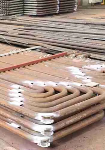
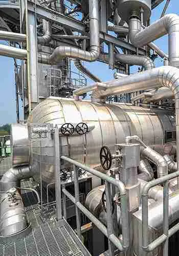
As the three core heating surfaces of a boiler, the economizer, water wall, and super-heater utilize the fundamental principle of counter-flow cascading heat exchange between flue gas and the working fluid. Connected in series along the water-steam path and absorbing heat in stages along the flue gas path, they divide the tasks of feed water preheating, water vaporization, and steam superheating. Their operating conditions are deeply coupled and mutually constrained, working in tandem to achieve highly efficient boiler thermal energy conversion and ensure a stable steam supply for the unit.
I. Core Flow Paths and Layout Logic (Counter-Flow & Cascading Utilization)
To maximize the recovery of flue gas waste heat, these three components strictly adhere to the matching principle of “high-temperature flue gas for high-temperature processes, and low-temperature flue gas for low-temperature processes.” Consequently, the direction of flue gas flow is completely opposite to that of the water-steam flow.
Flue Gas Flow (High to Low Temperature): Furnace High Temperature Flue Gas→ Water Wall→ Super-heater → Economizer → Stack (Chimney)
Water-Steam Flow (Low to High Temperature): Boiler feed water → Economizer (Preheating) → Steam Drum→ water wall (Steam Generation) → Drum Steam-Water Separation →super-heater (Temperature Rise) → Qualified super-heated Steam
II. Functional Division and Progressive Connection (Sequential & Layered Empowerment)
The functions of these three components do not overlap; instead, they progress step-by-step. The operating state of the upstream equipment directly dictates the operational baseline of the downstream equipment, forming a complete water-steam processing chain.
1. Economizer (Pre-stage Energy-Saving Preheating Unit)
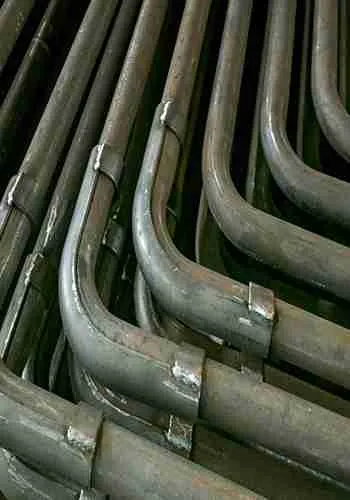
Located in the low-temperature flue gas zone at the rear of the boiler, the economizer is the very first heating equipment in the water-steam cycle. Its core function is to utilize the waste heat of low-temperature exhaust gas to heat the boiler feed water, thereby raising the inlet water temperature. This not only reduces exhaust gas heat loss and saves fuel, but also lessens the heating load on the water wall, providing optimal operating conditions for stable steam generation. The equipment itself only heats water and does not generate steam.
2. Water wall (Core Steam Generation Hub Unit)
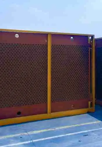
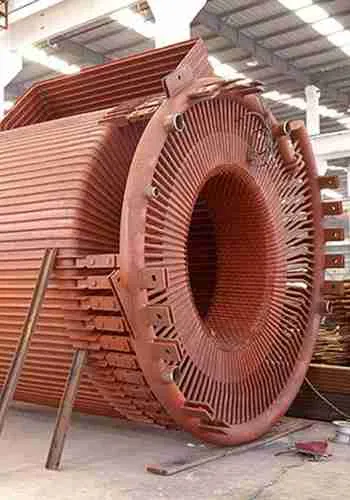
Arranged on the inner walls of the furnace, the water wall directly absorbs the high-temperature radiant heat from the furnace. It serves as the boiler’s sole primary evaporation heating surface, playing a pivotal role in connecting the upstream and downstream stages. It receives the preheated feed water from the economizer, heats it to a boil to generate a saturated steam-water mixture, and then delivers it to the steam drum where pure saturated steam is separated. By supplying the total raw steam required by the super-heater, it acts as the critical intermediate equipment linking feed water preheating to steam super heating.
3. Super–heater (Terminal Steam Quality Upgrading Unit)
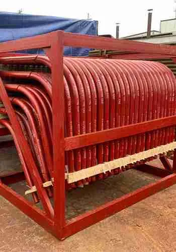
Positioned in the medium-temperature flue gas zone at the furnace outlet, the super-heater is a dedicated equipment for steam finishing and does not participate in the water vaporization process. Relying on the pure saturated steam produced by the water wall, it utilizes the heat of the medium-temperature flue gas to further elevate both temperature and pressure. This converts saturated steam into high-quality, high-temperature, and high-pressure super-heated steam that meets the standards for steam turbine power generation and industrial steam use. It serves as the final processing equipment for the boiler’s finished steam product.
III. Operational Interlock and Mutual Constraints (Condition Coupling & Chain Cascading Failures)
These three components operate within a closed-loop system where load changes trigger simultaneous responses. A failure in any single piece of equipment will cause a chain reaction affecting the other two, directly impacting boiler efficiency and operational safety.
Normal Load Coupling: When the boiler load increases, the fuel and flue gas volumes rise simultaneously. The economizer absorbs more heat, raising the feed water temperature; this optimizes the inlet conditions for the water wall, leading to a steady increase in steam production. Consequently, the parameters of the saturated steam rise in tandem, allowing the super-heater to absorb sufficient heat and ultimately output high-quality main steam in a well-matched, synchronized manner.
Chain Cascading Failures:
If the economizer’s heat exchange degrades, it results in low inlet water temperature for the waterwall and insufficient steam generation, which subsequently causes low inlet steam parameters for the superheater and substandard main steam quality.
Fouling, scaling, leakage, or tube bursts in the water wall will trigger a sharp drop in steam production or cause steam carryover (water in steam). This introduces liquid moisture into the super-heater, inducing over temperature, salt deposition, and tube bursting.
Ash accumulation or poor heat exchange in the super-heater will raise the flue gas exit temperature, which reduces the waste heat recovery efficiency of the economizer and increases overall boiler coal consumption.
IV. Holistic Summary
Together, these three components form a complete boiler heat exchange network: the economizer handles energy-saving preheating, the water wall manages core steam generation, and the super-heater takes charge of steam quality upgrading. Structurally arranged in series, functionally progressive step-by-step, and operationally interdependent, they maximize the utilization of flue gas waste heat through counter-flow cascading heat exchange. Ultimately, they collectively dictate the boiler’s thermal efficiency, steam quality, and operational safety.