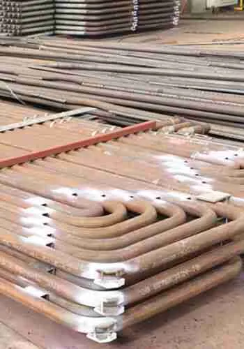
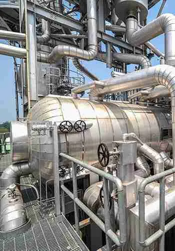
As a critical pressure-retaining waste heat recovery component in boiler systems, the core design of an economizer aims to ensure operational safety and equipment durability while balancing heat transfer efficiency, low resistance, and low operation and maintenance (O&M) costs. Key focus areas include preventing common failures such as low-temperature corrosion, erosion wear, ash accumulation/tube plugging, flow-induced vibration, excessive resistance, and thermal stress cracking.
The following six dimensions outline standardized, practical, and refined design essentials.
1. Material Selection: Match Working Conditions to Prevent Corrosion Failure
Material selection directly determines the service life of an economizer. It must be precisely chosen based on flue gas temperature, sulfur content, dust concentration, feedwater quality, and system pressure levels, with a focus on controlling low-temperature dew point corrosion and tube wall erosion/corrosion.
Low-Temperature Economizers (Flue gas temperature ≤ 350°C): For high-sulfur flue gas conditions (such as coal-fired or biomass boilers), ND steel (09CrCuSb) is preferred to significantly enhance resistance to low-temperature dew point corrosion and effectively prevent tube wall perforation from sulfidation. For systems with high dissolved oxygen in feedwater or poor water quality, match it with corrosion-resistant tube materials to avoid internal wall oxidation, scaling, and clogging.
Medium-to-High Temperature Economizers (Flue gas temperature > 350°C): For clean, low-dust flue gas conditions, 20# seamless steel pipes are selected to meet system pressure and high-temperature heat exchange requirements. For pulverized coal or high-erosion conditions, upgrade to wear-resistant alloy materials to improve the erosion resistance of the tube bundles.
Fin and Auxiliary Material Selection: Fin materials must match the base tube material to prevent galvanic electrochemical corrosion caused by contacting dissimilar metals. Fin spacing should be reasonably controlled; for standard conditions, it is set to 4–6 mm to balance ash accumulation prevention and heat transfer efficiency, preventing ash plugging and heat transfer deterioration caused by tight spacing.
2. Structural Design: Balance Heat Transfer Efficiency, Operational Resistance, and Structural Stability
The core of structural design is high efficiency, low resistance, and structural reliability. Key focuses include optimizing tube bundle layout, anti-vibration structures, thermal compensation, and sealing design to eliminate issues like flue gas short-circuiting, vibration cracking, and thermal deformation damage.
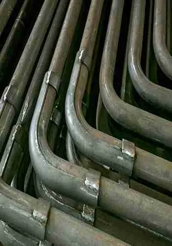
Tube Type and Bundle Arrangement: Prefers H-type finned tubes or spiral finned tubes over traditional bare tubes, increasing the effective heat transfer area by 30%–50% while disrupting the flue gas boundary layer via fin turbulence to enhance heat transfer. Staggered tube layouts are used for high heat-exchange demands, while in-line arrangements can be used in clean, low-dust conditions to reduce flue gas resistance. Maintain uniform tube row spacing throughout to eliminate local flue gas velocity inequalities and localized erosion from gas bias.
Anti-Vibration Design: Precisely avoid Von Kármán vortex street resonance risks by setting reasonable tube bundle spans. Use intermediate supports, anti-vibration bars, and fixed tie rods to constrain tube bundle swaying. Rigorously verify flue gas velocity to steer clear of fluid resonance velocity ranges, preventing fatigue cracking caused by long-term alternating loads on tube walls and welds.
Thermal Expansion Compensation Design: To address the significant thermal expansion and contraction caused by boiler startups, shutdowns, and load fluctuations, equip the system with independent expansion joints and floating header structures. This effectively absorbs the differential thermal deformation between the tube bundles and the shell, preventing tube end cracking, weld tearing, and header deformation.
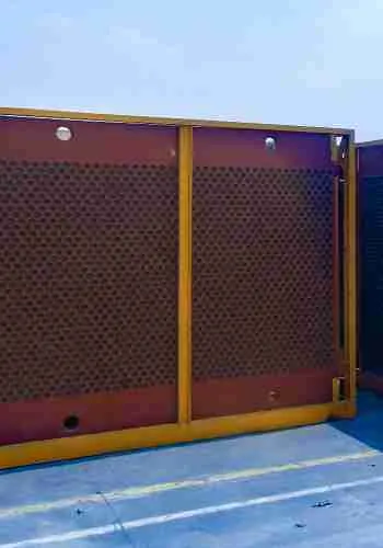
Sealing and Flue Gas Corridor Prevention: Fully seal the gaps between the tube bundles and the furnace wall, as well as between individual tube bundles. Install baffle plates and sealing plates to eliminate flue gas short-circuiting and localized high-speed erosion, ensuring that the flue gas flows uniformly through all heat exchange tube bundles to guarantee overall thermal efficiency.
3. Thermal and Hydraulic Calculations: Precisely Match System Operating Parameters
Precise thermal and hydraulic calculations are key to the stable operation of the economizer. Parameter deviations can easily cause insufficient heat transfer, excessive resistance, high energy consumption, and water hammer tube bursts. Calculations must strictly match the boiler’s rated operating conditions.
Heat Transfer Area Verification: Calculate the heat transfer area precisely based on the boiler’s rated load, inlet/outlet flue gas temperatures, and water temperatures, reserving a 5%–10% design margin to offset heat transfer degradation caused by long-term ash accumulation and load fluctuations. Reasonably control the exhaust gas temperature to avoid both the low-temperature corrosion zone and energy waste from excessive exhaust temperatures.
System Resistance Control: Verify the operating resistance on both the flue gas side and the water side. Flue gas side resistance must match the rated head of the induced draft fan (IDF), and water side resistance must meet the feed pump operating conditions to prevent excessive resistance from causing spikes in fan/pump energy consumption or restricting boiler output.
Pressure Rating Matching: The design pressure of the economizer must be higher than the maximum working pressure of the boiler, leaving a sufficient safety margin. Strictly distinguish between high and low pressure ratings; low-pressure economizers are strictly prohibited in high-pressure systems to prevent catastrophic tube burst accidents.
Water Temperature and Boiling Control: For non-boiling economizers, the outlet water temperature must be 20–30°C lower than the saturation temperature at the corresponding pressure to prevent water flashing into steam, which causes steam pockets, water hammer, and tube bundle vibration damage. For boiling economizers, the boiling rate must be precisely controlled, and reliable steam-water separation structures must be provided to ensure stable operation.
4. Protection Design: Systematically Resolve Erosion, Ash Accumulation, and Corrosion
Industrial flue gas from coal or biomass generally contains dust and sulfides. Target protection design is a core step to extend the service life of the economizer and reduce unplanned shutdowns.
Erosion-Resistant Design: Install erosion shields (wear shields), protective plates, and guide vanes in high-erosion areas such as the flue gas inlet, tube bundle bends, and the first row of tubes. Under high-dust conditions, appropriately lower the baseline flue gas velocity to mitigate dust erosion. Increase tube wall thickness at highly wearable locations to facilitate future maintenance and replacement.
Soot/Ash Accumulation Prevention Design: Optimize fin spacing and tube bundle gaps to eliminate dead zones for ash accumulation. Pre-reserve standardized installation positions for soot blowers, adapting to steam blowing, sonic blowing, and other equipment to achieve full-coverage, blind-spot-free soot blowing. The structural design should avoid low-lying ash collection areas to prevent dust accumulation, caking, and tube plugging.
Low-Temperature Corrosion Prevention Design: Precisely calculate the flue gas dew point temperature to ensure that the tube wall working temperature always remains above it. For high-sulfur flue gas conditions, implement dual protection using “ND steel + optimized flue gas temperature control”. When necessary, add a flue gas bypass or a feedwater preheating device to completely bypass low-temperature corrosion operating zones.
5. Safety System Design: Comply with Pressure Equipment Regulations
Economizers are classified as pressure-retaining special equipment. The design must strictly follow boiler safety technical codes, and must include all necessary protection, emergency, and monitoring structures to safeguard equipment and system operations.
Bypass Emergency Structure: Non-boiling economizers must be equipped with a flue gas bypass duct and a feedwater bypass. During boiler ignition or low-load operation, the system can switch to bypass operation to prevent dry firing of the economizer and vaporization of water within the tubes. It also allows for isolated maintenance of the equipment without affecting basic boiler operation.
Safety Accessory Configuration: Install pressure gauges, thermometers, drain valves, and vent valves at the equipment inlet and outlet to achieve high-point venting and low-point draining, eliminating air pocketing, water accumulation, and scaling inside the tubes. High-pressure systems must be equipped with safety valves and overpressure protection devices to meet compliance requirements for pressure equipment.
Weld and Structural Safety: All pressure-retaining welds must meet non-destructive testing (NDT) standards. Membrane economizers should focus on optimizing weld structures to prevent stress concentration cracking. Supports, hangers, and tube clamps must be verified for strength under dynamic-static combined loads to prevent deformation or detachment during operation, ensuring structural stability.
6. Installation and O&M Adaptation Design: Lower Life-Cycle Costs
The design must consider the entire workflow of manufacturing, transportation, on-site installation, and maintenance. Structural optimization improves buildability and maintainability, reducing later O&M costs.
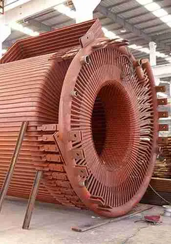
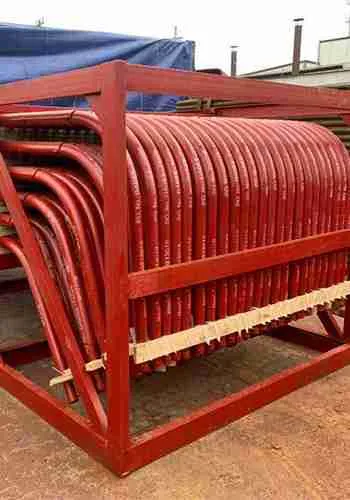
Modular Integrated Design: Large-scale economizers adopt a split modular structure combined with standardized flange connections. This enables factory prefabrication and rapid on-site lifting and splicing, simplifying construction while making single-module maintenance and replacement easier.
Maintenance Access Provision: Pre-reserve standard maintenance clearance around the equipment, and equip it with maintenance manholes and inspection windows. This allows visual tracking of tube wall wear, corrosion, and ash accumulation, meeting the requirements for wall thickness measurement, weld inspection, and component replacement.
Support System Optimization: Set up independent structural supports to prevent transferring the equipment’s weight onto the boiler proper. The overall support system should receive anti-corrosion and vibration-damping treatments to withstand long-term operational vibration and flue gas corrosion, guaranteeing long-term structural stability.